- Operating Systems Course
- Operating System Tutorial
- History of Operating System
- Personal Computer OS
- OS Processes
- OS Process Model
- OS Process Creation
- OS Deadlocks
- OS Deadlock Recovery
- OS Two-Phase Locking
- OS Memory Management
- OS Mono programming
- OS Shared Pages
- Operating System Input/Output
- OS Input/Output Devices
- OS Input/Output Software Layers
- OS Disk Hardware
- OS Files
- OS File Naming
- OS File Types
- OS Hierarchical Directory System
- OS Directory Operations
- OS File Operations
- Multimedia Operating System
- OS Multiprocessors
- Operating System Security
- OS User Authentication
- OS Trap Doors
- OS Viruses
Input/Output Management in Operating System
This post was written and published to describe how an operating system manages input and output. If we talk about the course "operating system," this is one of the most important topics in my opinion. Before we begin, please keep in mind that this post will most likely become a little longer, so be prepared. It might take a little more time, but I am confident that you will learn a lot from this post. Let's get started.
Controlling all of a computer's input and output devices is one of the primary or main functions of an OS, or operating system.
The operating system must issue the commands to the input and output devices, catch the interrupts, and handle the errors.
In addition, the operating system should act as a bridge between the input/output devices and the rest of the computer system. This interface should be straightforward, device-independent (where possible), and simple to use.
In any computer system, there are far too many input/output devices, such as discs, keyboards, monitors, and so on.
In this post, you will learn everything there is to know about input and output in operating systems. The following are the topics covered in this post:
- Input/Output Devices
- Device Controllers
- Memory Mapped Input/Output
- Direct Memory Access (DMA)
- Input/Output Software Goals
- Programmed Input/Output
- Input/Output Software Layers
- Disks
- Clocks
- Character Oriented Terminals
- Graphical User Interface (GUI)
- Network Terminals
- Power Management
Device Controllers
The input/output units consist of the following two parts:
- Mechanical component
- Electronic component (device controller)
Basically, device controllers are the electronic components of input and output units. Device controllers can also be called adapters.
The mechanical component of the input/output unit is the device itself, whereas the electronic component, device controller, or adapter takes the form of a printed circuit card that can be inserted into an expansion slot.
In most cases, the controller card will include a connector on it solely for the purpose of facilitating the act of plugging the cable that leads to the device. Controllers are able to manage a large number of devices that are identical.
Memory Mapped Input/Output
To communicate with the Central Processing Unit (CPU), each controller has a few registers. Many devices have data buffers that the operating system can read and write to.
The central processing unit (CPU) communicates with control registers and device data buffers in two ways, each discussed here one by one. Now let's talk about the first way.
Each control register is assigned an input or output port number. Special instructions such as
IN REG, PORT,
The central processing unit can read register PORT and store the result in register REG on the central processing unit. Similarly, the special instructions like
OUT PORT, REG
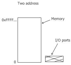
The central processing unit can write the contents of REG to a control register. This included all mainframe computers and the majority of early computers. In this way, the address spaces for memory and input/output are different, as shown in the figure given below:
Now, the following two instructions are given:
IN RO, 4
and
MOV RO, 4
are totally different in this design. The first instruction, that is,
IN RO, 4
reads the contents of input/output port 4 and puts it in RO, whereas the second instruction, that is,
MOV RO, 4
reads the contents of the memory word 4 and puts it in RO.
Now, let's talk about the second way, which is how the CPU communicates with the control registers and device data buffer. The second way, introduced with the PDP-11, is to map all the control registers into memory space, as shown in the figure below:
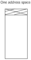
In this case, each control register is assigned a unique memory address to which no memory is assigned.
Memory-mapped input and output (MIOO) is the name given to this system. Generally, the assigned address is at the top of the address space.
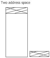
The figure given below shows a hybrid scheme with memory-mapped input and output data buffers and separate input and output ports for control registers.
Direct Memory Access
It doesn't matter whether a central processing unit (CPU) has or does not have memory-mapped input and output; it needs the device controllers to exchange data with them.
The central processing unit can request data from an input/output controller one byte at a time. But it wastes time on doing this; therefore, a different way is used called "Direct Memory Access" (DMA).
The OS can use direct memory access only if the hardware has a direct memory access controller.
The direct memory access controller can be integrated into disk or other controllers. But this type of design requires a separate direct memory access controller for each device.
Generally, a single direct memory access (DMA) controller is available for regulating transfers to more than one device or multiple devices, sometimes at the same time.
It doesn't matter where the direct memory access controller is physically located; it has access to the system bus independent of the central processing unit, as shown in the figure given below:
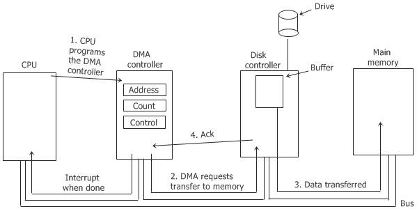
The direct memory access controller contains the following several registers that can be written to and read by the central processing unit:
- Memory address register
- Byte count register
- One or more control registers
Here, the control register(s) tell the computer which input/output port to use, the direction of the transfer, the size of the transfer, and how many bytes to send in one burst.
Input/Output Software Goals
Device independence is the main goal when designing input/output software. Here, device independence means that it should be possible to write computer programs that can access any input or output device without having to specify the device in advance.
Here is a list of some important issues for input/output software:
- Error handling
- Synchronous versus asynchronous transfers
- Buffering
Here, synchronous versus asynchronous transfers can also be called blocking versus interrupt-driven transfers. The table given below describes the above-listed three issues for input/output software:
| Input/Output Software Issue | Description |
|---|---|
| Error Handling | Generally, errors should be handled as close as possible to the computer hardware. If the controller discovers a read error, it should try to correct the error itself if it controller discovers a read error, it should try to correct the error itself if it can. And if it can't, then the device driver should handle it. |
| Synchronous Vs. Asynchronous | Most physical input and output are asynchronous. The central processing unit starts the transfer and goes off to do something else until the interrupt arrives. User programs are much easier to write when input/output operations are blocked.After a read system call, the program stops running until the data is in the buffer. Basically, it is up to the OS to make the operations that are really asynchronous look blocking to the user programs. |
| Buffering | Data that comes off a device cannot always be stored directly in its final destination. Buffering sometimes has a major impact on the system's input and output performance because it involves considerable copying. |
Programmed Input/Output
Fundamentally, input and output can be performed in one of the following two ways:
This section will teach us about the first method of performing the input or output, which is to program the input or output. The simplest way to do either is with programmed input and output.
The simplest way to handle input and output is to have the central processing unit (CPU) handle everything, including program input and output. The figure given below shows the steps to print a story of six characters in program input/output.
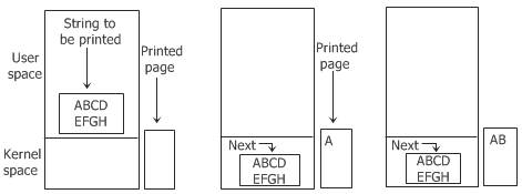
The following code describes or summarizes the action taken by the OS in response to programmed input and output:
copy_from_user(buffer, p, count);
for(i=0; i<count; i++)    // loop on every character
{
   while(*printer_status_reg != READY);    // loop until ready
   *printer_data_register = p[i];    // output one character
}
return_to_user();
Here, p is the kernel buffer. The programmed input/output is undeniably simple, but it has the significant disadvantage of occupying the CPU entirely until all of the input/output is completed.
Interrupt-Driven Input/Output
Interrupt-driven input or output is another way to perform input or output. In the case of printing on a printer that doesn't buffer the characters but prints each character as it arrives.
Each character takes 10 msec to print if the printer can print 100 characters per second.It means that after every character is written to the data register of the printer, the central processing unit will sit in an idle loop for 10 msec, waiting to be allowed to output the next character.
This 10 msec is much more time to do a context switch and run some other process, which would be wasted.
Interrupts are used to allow the central processing unit to do something or run another process while waiting for the printer to be read.
When the computer system call to print the string is made, the buffer is copied to the kernel space, and the first character is copied to the printer as soon as it is willing to accept a character. Now, at that point, the central processing unit (CPU) calls the scheduler, and then some other process is run. And, in this case, the process that was invoked to print the required string on the printer is halted until the entire string has been printed.
The code given below shows the work done on the system call.
copy_from_user(buffer, p, count);
enable_interrupts();
while(*printer_status_reg != READY);
*printer_data_register = p[0];
scheduler();
Now, when the printer has printed the character and is prepared to accept the next character from the string, it generates an interrupt.
Here, the interrupt now stops the current process and saves its state. The printer interrupt service procedure is then executed. Here is the code that shows this process of printing the string on the printer:
if(count == 0)
{
   unblock_user();
}
else
{
   *printer_data_register = p[i];
   count--;
   i++;
}
acknowledge_interrupt();
return_from_interrupt();
Now, if no characters remain to print from the required string, then the interrupt handler takes an action to unblock the user. Otherwise, it outputs the next remaining character from the string, acknowledges the interrupts, and returns to the process that was running just before the interrupt, which continues from where it left off.
A big disadvantage of interrupt-driven input and output is that an interrupt occurs on every character of the string. And as you know, interrupting takes time, so this method wastes a lot of central processing unit (CPU) time. Therefore, a solution to this problem is to use DMA. We will learn about input and output using DMA (Direct Memory Access) in the next section.
Input/Output using DMA
Input and output using Direct Memory Access (DMA) is another way to perform input and output.
Interrupt-driven input and output wastes CPU time, as you already know from the previous section. Therefore, now the idea is to let the direct memory access (DMA) controller feed the characters to the printer one at a time without wasting any CPU time.
The code given below shows this method of input and output using direct memory access (DMA). Code is executed when the print system call is made.
copy_from_user(buffer, p, count);
set_up_DMA_controller();
scheduler();
Interrupt service procedure.
acknowledge_interrupt();
unblock_user();
return_from_interrupt();
Disks
There are many distinct varieties of discs. The magnetic disc is the most typical of all of these different types.
When it comes to the distribution of programs, data, and videos, a number of different kinds of optical discs, such as CD-ROMs, DVDs, and CD-Recordables, all play an important role.
You will learn briefly about discs in the operating system, with the information being broken down into the following sections:
The "disc hardware" topic is covered in its own post (the next article), whereas the other two topics are covered in the following section.
Disk Formatting
A hard disc is made up of a stack of aluminum, alloy, or glass platters that are 5.25, 3.5, or even smaller in diameter. On each platter, a thin layer of magnetizable metal oxide is deposited. After the manufacturing process is complete, the disc contains absolutely no information of any kind.
Each platter of the disc must receive a low-level format done by the software before the disc can be used.
The format consists of a series of concentric tracks, where each track contains some number of sectors with short gaps between the sectors.
The figure given below shows the format of a sector:

Doing a high-level format on each partition is the last step in making a disc that can be used. This high-level format operation creates a boot block, a free storage management system, a root directory, and an empty file system.
The high-level format operation also puts a code in the partition table entry telling which file system is used in the partition because many OSs support multiple incompatible file systems. Therefore, at this point, the computer system can be booted.
Now, when the power of the computer system is turned on, the BIOS runs initially and then reads in the master boot record and jumps to it. This boot program then checks to see which partition is active. Now, after checking the partition for its activeness, it reads the boot sector from that partition and runs it.
Basically, the boot sector of a computer system contains a small code that searches the root directory for a specific program. That certain program is then loaded into memory and executed.
Stable Storage
The storage of data that is reliable is what is meant by the term "stable storage." It is essential for some computer applications that data never be lost or corrupted, even in the face of disc and central processing unit (CPU) errors.
Essentially, a disc should always function correctly.But unfortunately, it is not achievable.
Basically a disk should works all the time without any errors. But unfortunately it is not achievable. Here, achievable is a disc subsystem that has this property: when a write is issued to the disk, the disc either correctly writes the data or does nothing, leaving the existing data intact. Technically, this type of system is also called "stable storage."
Basically, stable storage uses a pair of identical discs with corresponding blocks working together to form an error-free block.
The corresponding blocks on both drives are the same in the absence of errors. Either one can get the same result.
Clocks
There are many reasons why clocks are essential to the operation of any multiprogrammed system. Clocks maintain the time of day and prevent one process from monopolising the central processing unit, among other things.
The clock software can take the form of a device driver, even though a clock is neither a block device nor a character device like a disc or mouse.
Now let's talk about the clock software or clock driver.
Clock Driver
The work of the clock driver varies among OSs. But the clock driver's work generally includes the following:
- keeps the time of day
- Prevents processes from running for longer than is specified or permitted.
- Accounts for the use of the central processing unit
- Profiling, monitoring, and statistics gathering
Character Oriented Terminals
Terminals are devices such as keyboards, monitors, and so on. Every computer system has at least one keyboard and one display for communication.
There are various types of terminals, or terminals come in various shapes and sizes. The three most important types of terminals are listed below:
- Standalone mainframe terminals with RS-232
- serial interfaces GUI-enabled PC displays
- Network terminals
PC refers to a personal computer, and GUI refers to a graphical user interface.
RS-232 Terminal Hardware
Basically, RS-232 terminals are the hardware devices that contain a keyboard and a display and communicate using a serial interface, one bit at a time.
These terminals use a 9- and 25-pin connector, where one pin is for transmitting the data, one is for receiving the data, and one is ground. The other pins are used for various control functions, most of which are not used.
Serial Lines
Serial lines are lines in which characters are sent one bit at a time. All the modems use this interface.
To send a character to an RS-232 terminal or modem over the serial line, the computer system must transmit it one bit at a time, preceded by a start bit and followed by 1/2 stop bits to delimit the character.
To allow a remote user to communicate with the mainframe computer world, RS-232 terminals are still commonly used.
Even when they are replaced by PCs, the PCs often just act like the old RS-232 terminals so that the mainframe software doesn't have to be changed.
GUI
The abbreviation for "graphical user interface" is "GUI." A GUI is used on virtually all personal computers sold in the modern era of computing.
When people first started using personal computers, the most common operating system was called MS-DOS, and it featured a character-based user interface. Here, MS-DOS stands for Microsoft Disk Operating System.
The following four components make up an essential part of any graphical user interface:
- Windows
- Icons
- Menus
- Pointing device
In a nutshell, these four indispensable components of a graphical user interface are collectively referred to as WIMP, which is an abbreviation for windows, icons, menus, and pointing devices.
Network Terminals
Network terminals serve the purpose of establishing a connection between a remote user and a computer via a network. There are two types of networks: local area networks and wide area networks (WAN). There are two main ideas that illustrate how the network terminal is supposed to function:
- In order for the network terminal to successfully execute the complex protocols that reduce the amount of data that is transmitted over the network, the terminal should have a significant amount of both processing power and memory.
- In order to keep costs down, the network terminal just displays pixels without doing much thinking. This makes it very easy to use.
Power Management
kilowatts of power because it had 18 thousand vacuum tubes. Therefore, due to consuming such a high amount of wattage, it produced a non-trivial electricity bill. After that, there was the invention of the transistor, and the power usage dropped by a large amount.
Now, in today's computer world, power management is a very useful task for many reasons. OS is playing a big role in power management. Generally, a desktop personal computer has a 100- or 200-watt power supply.
Let's suppose that if 100 million personal computers, each with a 200-watt power supply, were turned on at the same time around the world, they would use a combined 20 thousand megawatts of electricity. And this is the total output of 20 nuclear power plants of average size.
Now, if the power supply could be cut in half, we could get rid of almost 10 average-sized nuclear power plants.
Battery-powered computer systems such as laptops, notebooks, palmtops, etc. are another place where power is a big issue. Therefore, power management is also essential in these types of computer systems.
The main problem with these types of battery-powered computer systems is that the batteries can't hold enough charge to last very long-a few more hours.
As a result, everyone's main goal in developing battery-powered computer systems that use less energy is to make the existing batteries last longer.
The operating system (OS) plays a major role here in saving the battery so it can be used for more time.
In general, two things can be done to reduce energy consumption:
- for the operating system to turn off all computer system components that are not in use or when they are not in use. The turned-off device or part uses little or no energy.
- Application programs can use less energy by degrading the quality of the user experience to increase battery life.
« Previous Topic Next Topic »